精密轴承制造生产场景

Bearing Selection and Maintenance for Metallurgical Equipment: A Practical Guide for High-Temperature, Heavy-Load and Dusty Environments

Bearing Selection and Maintenance for Metallurgical Equipment: A Practical Guide for High-Temperature, Heavy-Load and Dusty Environments

The metallurgical industry is one of the most demanding application environments for bearings. From blast furnace top equipment to hot strip rolling lines, from continuous casters to cold rolling mills, bearings must maintain long-term stable operation under multiple severe conditions including high temperature, heavy loads, dust and moisture attack. Once a bearing fails, the consequences can range from shutdown of a single machine to unplanned stoppage of an entire production line, resulting in enormous economic losses.

1. Four Major Challenges Facing Metallurgical Bearings

  • High-temperature environment: Bearing housing temperatures on hot rolling lines can reach 150–200°C, and are even higher in continuous casting areas. High temperature accelerates lubricant degradation, alters bearing clearance and reduces material hardness.
  • Heavy impact loads: Peak loads during the rolling process can reach 3–5 times the rated load, placing extremely high demands on the bearing’s impact resistance.
  • Contamination ingress: Contaminants such as mill scale, metal dust, cooling water and rolling oil can easily penetrate the bearing interior, accelerating wear and corrosion.
  • Low-speed oscillation: Equipment such as oscillating shears operates under heavy loads at extremely low speeds, which is detrimental to the stable formation of a lubricating film.
Metallurgical equipment bearing applications
Bearings in the metallurgical industry must operate stably over the long term under multiple severe conditions such as high temperature, heavy loads and contamination

2. Key Bearing Selection Parameters for Metallurgical Applications

1. Bearing Type Selection

Four-row tapered roller bearings and double-row cylindrical roller bearings are the mainstream solutions for rolling mill roll neck bearings, offering high load capacity and excellent impact resistance. Thrust roller bearings are used to accommodate axial loads. For space-constrained applications, high-capacity angular contact ball bearings can serve as an alternative. Boxier’s NN-series double-row cylindrical roller bearings and BAR-series thrust angular contact ball bearings can both meet the selection requirements of metallurgical equipment.

2. Determination of Clearance Grade

Metallurgical bearings typically require a larger clearance of C3 or C4 grade to compensate for the clearance reduction caused by thermal expansion at high temperatures. However, excessive clearance in turn reduces bearing rigidity and rotational accuracy, so the clearance must be precisely determined through thermal balance calculations based on the specific operating conditions.

3. Material and Heat Treatment

High-quality metallurgical bearings are typically manufactured from high-temperature-resistant carburizing steel or bainite-quenched steel, ensuring that sufficient hardness and dimensional stability are maintained even at 200°C. Boxier can provide customized bearing products with special materials and heat treatments upon customer request.

3. Scientific Maintenance Strategies for Metallurgical Bearings

  • Lubrication management: Lithium-based grease with extreme pressure (EP) additives is recommended, with regreasing intervals determined by operating temperature and duty time. Oil-air lubrication systems are recommended for high-speed rolling mills.
  • Sealing protection: A dual sealing arrangement combining labyrinth seals and skeleton oil seals is adopted, with seal wear inspected on a monthly basis.
  • Online monitoring: Install bearing vibration sensors and temperature sensors, build an equipment condition database, and achieve predictive maintenance.
  • Regular oil analysis: Conduct spectroscopic and ferrographic oil analysis on a quarterly basis to assess bearing health through wear particle characteristics.
  • Scheduled replacement: Develop a scheduled replacement plan based on operating hours rather than failure signals.

Summary: Bearing selection for metallurgical equipment is a comprehensive balance among load capacity, high-temperature resistance, contamination resistance and cost-effectiveness. Boxier Precision Bearings provides specialized bearing products and technical support for the metallurgical industry, helping customers significantly reduce unplanned equipment downtime, extend bearing service life, and achieve cost reduction and efficiency improvement. For selection advice or technical support, please feel free to contact us.
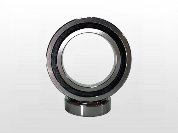
70系列精密角接触球轴承产品图

Angular Contact Bearing Contact Angles 15°/25°/40° Explained: No More Hesitation in Selection

Angular Contact Bearing Contact Angles 15°/25°/40° Explained: No More Hesitation in Selection

The contact angle is the most critical design parameter of angular contact ball bearings, as it directly determines the bearing’s axial load capacity, limiting speed and overall rigidity characteristics. Faced with the three mainstream contact angle options of 15°, 25° and 40°, many engineers find it difficult to decide. This article systematically analyzes the technical characteristics of different contact angles from the perspective of mechanical principles, helping engineers make scientific and informed decisions.

1. Mechanical Principles of the Contact Angle

The contact angle is the angle between the normal line at the contact point of the rolling elements and raceway and the radial plane of the bearing. From a mechanical standpoint, this angle directly determines the load transmission path: the larger the contact angle, the higher the proportion of the axial force component, and the stronger the bearing’s axial load capacity. However, a larger contact angle also means that the balls are subjected to a greater centrifugal force component at high speed, resulting in a lower limiting speed. Therefore, the contact angle is essentially a trade-off between speed capability and load capacity.

Mechanical analysis diagram of angular contact bearing contact angle
Different contact angles form different trade-offs between axial load capacity and limiting speed

2. Detailed Comparative Analysis of the Three Contact Angles

1. 15° Contact Angle — The King of Ultra-High-Speed Applications

Bearings with a 15° contact angle have the smallest axial offset between the rolling elements and the raceway and the lowest centrifugal force effect at high speed, and therefore offer the highest limiting speed. However, their axial load capacity is also the weakest, and they typically need to work in combination with larger-angle bearings within a bearing set. The 15° contact angle bearing is an ideal choice for ultra-high-speed motorized spindles operating above 30,000 rpm and precision grinding head spindles. Boxier’s BER ultra-high-speed series and H719 series both offer 15° contact angle configurations.

2. 25° Contact Angle — The Most Balanced All-Rounder

The 25° contact angle achieves the best balance between speed and load capacity and is the most widely used contact angle standard for precision machine tool spindles. Whether for machining centers, milling spindles or precision grinding machines, the 25° contact angle delivers satisfactory overall performance. Boxier’s 718, 719 and 70 series precision bearings come standard with a 25° contact angle, meeting the operating requirements of most CNC machine tools.

3. 40° Contact Angle — The First Choice for Heavy-Load Applications

Bearings with a 40° contact angle offer the strongest axial load capacity and are particularly suitable for applications subjected to large axial loads, such as lathe spindles, vertical machining centers and heavy-duty milling machines. However, it should be noted that their limiting speed is significantly lower than that of small-angle bearings, making them suitable for medium- and low-speed heavy-load conditions. Boxier’s BTR series and BAR series thrust angular contact ball bearings feature large-angle designs that deliver outstanding axial load performance.

3. Practical Recommendations for Contact Angle Selection

Contact angle selection should follow these principles: first determine the spindle speed range and load characteristics, then select the optimal angle based on the contact angle–speed–load capacity curves; for complex conditions requiring both high speed and heavy loads, a combination of bearings with different contact angles can be adopted, with the larger-angle bearings carrying the main axial loads and the smaller-angle bearings ensuring high-speed capability; where conditions permit, finite element simulation analysis of the bearing arrangement is recommended to verify the feasibility of the selected configuration.

Summary: There is no absolutely optimal contact angle — only the choice that best matches the operating conditions. Boxier’s technical team is equipped with professional bearing selection calculation software and can quickly recommend the optimal contact angle configuration based on your specific speed, load and operating conditions. Please feel free to contact us for free selection support.

高速推力角接触球轴承产品图

Bearing Cage Material Comparison: How to Choose Between Stamped Steel, Brass and PEEK?

Bearing Cage Material Comparison: How to Choose Between Stamped Steel, Brass and PEEK?

The cage is an often-overlooked yet critically important component of a bearing. Although it does not carry load directly, it has a decisive influence on the bearing’s limiting speed, running noise, service life and overall reliability. Studies show that more than 90% of high-speed bearing failure cases are related to the cage. This article provides a systematic comparison of the performance characteristics and application scenarios of three mainstream cage materials: stamped steel, solid brass and PEEK.

1. Stamped Steel Cage — The Economical and Durable Basic Option

Stamped steel cages are formed from high-quality cold-rolled steel sheet through precision stamping, making them the most widely used cage type. Their core advantages are: high strength (approximately 2 to 3 times that of brass), which enables thinner cross-sections and leaves more space for rolling elements to increase load-carrying capacity; low cost, which suits mass production; and excellent impact resistance, allowing them to withstand significant vibration and shock loads. However, steel cages have a high density (7.8 g/cm³), producing a pronounced centrifugal force effect at high speeds, and the friction coefficient between steel and steel is relatively high. They are suitable for low-to-medium speed applications with a dmN value below 1 million and for applications subject to high vibration.

Comparison analysis of bearing cages made of different materials
The three cage types — stamped steel, brass and PEEK — differ significantly in density, strength and applicable speed range

2. Solid Brass Cage — The Classic Choice for Precision Bearings

Solid brass cages are produced by casting or precision machining and hold an irreplaceable position in the precision bearing field. Their outstanding advantages include: excellent wear resistance and damping characteristics that effectively absorb high-frequency vibration; a low friction coefficient between brass and steel balls that resists smearing under boundary lubrication conditions; and a thermal expansion coefficient close to that of bearing steel, delivering exceptional thermal stability across an operating temperature range from -40 °C to +300 °C. Although brass cages cost more than stamped steel cages, they remain the mainstream choice for medium-to-high speed applications such as precision machine tool spindles and high-speed motors, achieving dmN values of 1.3 to 1.5 million.

3. PEEK Cage — The Revolutionary Solution for the Ultra-High-Speed Era

PEEK (polyether ether ketone) is a high-performance engineering plastic whose application in bearing cages represents a major technological breakthrough in recent years. The core advantages of PEEK cages are impressive: a density of only 1.3 g/cm³ (about one-sixth that of steel), which can raise the limiting speed by 20 to 30%; excellent self-lubricating properties that maintain normal operation even under poor lubrication conditions; good elasticity and damping that effectively absorb vibration and shock; and temperature resistance of up to 260 °C with outstanding chemical corrosion resistance. PEEK cages are the standard configuration for ultra-high-speed bearings with dmN values above 1.6 million and are widely used in high-speed motorized spindles and the aerospace industry. However, it should be noted that their load-carrying capacity and impact resistance are inferior to those of metal cages.

4. Application Scenario Recommendations

General-purpose motors and pumps → stamped steel cage (low cost, high strength); precision machine tool spindles → solid brass cage (excellent wear resistance, superior thermal stability); high-speed motorized spindles (above 30,000 rpm) → PEEK cage (lightweight, self-lubricating); aerospace equipment → PEEK or brass cage (depending on the specific operating conditions); heavy-load, low-speed applications → stamped steel cage (highest strength).

Summary: Every product series from Boxier Precision Bearings offers multiple cage configuration options. The 718, 719 and 70 series come standard with solid brass cages and can be upgraded to PEEK cages; the BER and BNR ultra-high-speed series are equipped with PEEK cages as standard, fully meeting the requirements of all kinds of high-speed precision applications. Correct cage selection is a key step in ensuring reliable bearing operation.

金属加工与轴承制造工业场景

Common Failure Modes of Machine Tool Spindle Bearings and Systematic Prevention Strategies

Common Failure Modes of Machine Tool Spindle Bearings and Systematic Prevention Strategies

Bearing failure is the leading cause of machine tool spindle faults, accounting for more than 60% of all spindle failures. What deserves even more attention is that, according to statistics, over 90% of bearing failures are not caused by defects in the bearings themselves, but by human factors such as improper lubrication, contamination ingress or installation errors. This means that the vast majority of spindle bearing failures can be avoided through scientific management and standardized operating procedures.

1. Raceway Fatigue Flaking — The Most Typical Sign of End-of-Life

Raceway fatigue flaking manifests as fish-scale or flake-shaped metal spalling on the raceway surface, and is a normal failure mode that occurs after the bearing reaches the end of its fatigue life. However, if flaking appears when the actual operating time is far below the bearing’s design life, the following aspects should be investigated: whether the preload is excessive, causing contact stress to exceed permissible limits; whether lubrication is adequate and the oil film thick enough; and whether the installation is properly aligned or suffers from misalignment and uneven loading.

Precision machine tool spindle bearing
The reliable operation of machine tool spindle bearings directly affects machining quality and production efficiency

2. Cage Fracture — The Number One Risk in High-Speed Applications

Under high-speed operating conditions, the cage is subjected to enormous centrifugal forces and high-frequency vibration loads. Once the cage fractures, its fragments quickly damage the raceway and rolling element surfaces, causing the spindle to seize or even be scrapped. The key to preventing cage fracture lies in: selecting a cage material suited to the operating speed (PEEK or solid brass cages are superior to stamped steel cages); strictly controlling lubricant cleanliness and oil supply; and avoiding prolonged operation of the spindle in the critical speed range.

3. Wear and Scoring — The Chain Reaction of Contamination Ingress

Once hard particles (such as metal cutting chips and abrasive dust) enter the bearing interior, they cause abrasive wear and scoring on the raceway and rolling element surfaces, leading to increased vibration levels, reduced rotational accuracy and higher noise. Preventive measures include: selecting high-quality seals (such as contact seals or labyrinth seals); regularly changing the lubricating oil and testing oil cleanliness; and keeping the working environment and the coolant system clean.

4. Electric Erosion Failure — The Hidden Killer of the Variable-Frequency Era

With the widespread application of variable-frequency motors in machine tools, electric erosion failure caused by shaft currents has become increasingly prominent. When current passes through the bearing, electric sparks are generated between the raceways and rolling elements, forming regularly distributed pitted erosion craters. The most effective preventive measures are to use hybrid ceramic ball bearings (the ceramic balls insulate and interrupt the current path) or to install a grounding carbon brush system.

5. Systematic Preventive Measures

  • Scientific selection: choose the appropriate precision grade, clearance grade and cage material according to the actual operating conditions.
  • Standardized installation: strictly follow the installation procedures, use dedicated mounting tools, and record the assembled preload and clearance data.
  • Proper lubrication: select the lubrication method and lubricant based on speed and temperature, and establish a scheduled lubrication maintenance regime.
  • Condition monitoring: deploy vibration and temperature sensors, build a bearing operating condition database, and achieve predictive maintenance.
  • Failure analysis: conduct root cause analysis for every bearing failure, document the failure modes and causes, and continuously improve selection and maintenance strategies.

Summary: If your equipment exhibits abnormal bearing vibration or temperature rise, it is recommended to stop the machine immediately and inspect it. Boxier Precision Bearings provides professional bearing failure analysis services to help customers quickly locate the root cause of faults and propose systematic improvement recommendations, fundamentally reducing the risk of bearing failure.

CNC数控机床加工精密轴承部件

Hybrid Ceramic vs. Steel Ball Bearings: A Comprehensive Comparison for High-Speed Precision Applications

Hybrid Ceramic vs. Steel Ball Bearings: A Comprehensive Comparison for High-Speed Precision Applications

When spindle speeds break through the 30,000 rpm threshold, the behavior of conventional steel balls under enormous centrifugal force begins to bottleneck system performance. The high density of steel balls causes a sharp rise in centrifugal force, which dramatically increases internal contact stresses in the bearing, intensifies heat generation, and in severe cases can even lead to cage fracture. Hybrid ceramic ball bearings were developed precisely in response to this technical demand as the high-speed solution.

1. Core Advantages of Ceramic Materials

The ceramic material predominantly used in precision bearings today is silicon nitride (Si₃N₄). Compared with conventional bearing steel GCr15, silicon nitride exhibits a remarkable set of physical properties: a density of only 3.2 g/cm³, just 40% that of steel; an elastic modulus 50% higher than steel; a coefficient of thermal expansion only one-quarter that of steel; and a hardness more than twice that of steel. These characteristics greatly reduce the centrifugal force acting on ceramic balls at high rotational speeds. Combined with a PEEK cage, the limiting speed is increased by more than 30% over steel ball bearings of the same size.

Comparison of ceramic ball and steel ball bearing materials
Silicon nitride ceramic balls offer significant advantages over bearing steel in density, hardness and thermal properties

2. Five Key Advantages of Hybrid Ceramic Bearings

  • Limiting speed increased by 20–30%: The low density of ceramic balls greatly reduces centrifugal force at high rotational speeds.
  • Lower temperature rise: The low coefficient of friction between ceramic balls and steel raceways generates less frictional heat, providing better thermal stability.
  • Superior resistance to seizure on sudden stops: Under extreme conditions of lubrication failure, ceramic balls will not cold-weld or adhere to the steel raceways.
  • Electrical insulation against electric erosion: Ceramic is a natural electrical insulator that effectively prevents shaft currents from eroding the bearing.
  • Extended lubrication life: The smoother surface of ceramic balls reduces shear losses of the lubricant, prolonging the grease relubrication interval.

3. Where Steel Ball Bearings Are the Better Choice

Although ceramic ball bearings perform exceptionally well in high-speed applications, steel ball bearings remain the better choice in the following cases: applications subject to severe impact loads (ceramic balls have lower toughness than steel balls and may fracture); low-speed, heavy-load conditions (where the high-rigidity advantage of ceramics cannot be fully exploited); cost-sensitive projects (hybrid ceramic ball bearings cost approximately 3–5 times as much as steel ball bearings of the same size); and extra-large bearings (the ceramic ball manufacturing process limits the availability of large-diameter balls).

4. Boxier’s Hybrid Ceramic Bearing Solutions

Boxier Precision Bearings offers hybrid ceramic ball bearing options across multiple ultra-high-speed series, including BER, BNR, H70 and H719. Built on a proven technology platform combining high-quality silicon nitride ceramic balls, precision-ground steel rings and PEEK cages, these products have operated reliably over the long term in high-speed motorized spindles, precision grinder spindles and aero-engine applications, achieving limiting speeds with dmN values above 1.6 million.

Summary: For high-speed precision applications requiring speeds beyond the limits of conventional steel ball bearings, hybrid ceramic ball bearings are currently the most mature and reliable upgrade solution. For specific selection recommendations, please contact the Boxier technical team for detailed technical specifications and comparative analysis.

精密机床设备与主轴轴承应用

Motorized Spindle Bearing Selection: Striking the Optimal Balance Between Speed, Rigidity and Service Life

Motorized Spindle Bearing Selection: Striking the Optimal Balance Between Speed, Rigidity and Service Life

As the core power unit of modern high-speed machining centers, the performance of a motorized spindle depends largely on the choice of bearings. A motorized spindle running at 30,000 rpm already exceeds a bearing dn value of one million, placing extremely high demands on bearing design, materials and manufacturing processes. Finding the optimal balance among speed, rigidity and fatigue life is an unavoidable core challenge in motorized spindle design.

1. Four Core Requirements for Motorized Spindle Bearings

  • High limiting speed: Modern motorized spindles typically operate at 10,000–100,000 rpm, requiring bearings with excellent high-speed performance.
  • High rotational accuracy: Spindle nose runout must generally be held within 2–5 µm, as it directly determines workpiece machining accuracy.
  • High rigidity: Sufficient system rigidity prevents chatter during cutting and ensures surface finish quality.
  • Low heat generation and long service life: Thermal management at high speeds is one of the greatest challenges in motorized spindle design.
Application of high-speed motorized spindle bearings
High-speed motorized spindle bearings must maintain stable operation under extremely demanding conditions

2. Key Selection Parameters Explained

1. Contact Angle Selection Strategy

The contact angle is the most critical parameter of angular contact ball bearings. Bearings with a 15° contact angle offer the highest limiting speed but the weakest axial rigidity, making them suitable for ultra-high-speed, light-load motorized spindles (above 30,000 rpm). The 25° contact angle is currently the most mainstream choice for high-speed motorized spindles, achieving the optimal balance between speed and rigidity. The 40° contact angle provides the greatest axial rigidity but a lower limiting speed, and is suited to heavy-load, low-speed spindles.

2. How Cage Material Constrains Performance

A standard pressed steel cage has a dmN limit of approximately one million, while a machined brass cage can reach 1.3–1.5 million. A PEEK engineering plastic cage, thanks to its light weight (density only one-sixth that of steel) and self-lubricating properties, can push the dmN value above 1.6 million. For ultra-high-speed motorized spindles operating beyond 30,000 rpm, the PEEK cage is unquestionably the first-choice solution.

3. Selecting and Optimizing Preload Methods

Fixed-position preload offers a simple structure and low cost, but is strongly affected by temperature, making it suitable for low- to medium-speed applications. Constant-pressure preload applies a constant preload force through springs; it provides excellent thermal stability and is widely used on high-speed spindles. The latest hydraulic preload technology can adjust the preload force in real time during operation, achieving a dynamic balance between speed and rigidity, and represents the development direction of high-end motorized spindles.

3. Typical Motorized Spindle Bearing Configurations

  • Ultra-high-speed grinding spindles (30,000–60,000 rpm): 719 series or BER series angular contact ball bearings are recommended, with accuracy of P4 or higher, PEEK cages, oil-air lubrication and light preload.
  • Machining center spindles (10,000–20,000 rpm): 70 series or BTR series bearings are recommended, in a back-to-back arrangement, with grease or oil-air lubrication and medium preload.
  • Engraving machine motorized spindles (20,000–40,000 rpm): H70 or H719 ultra-high-speed series are recommended, with light preload, oil-air lubrication and PEEK cages.
  • Heavy-duty milling spindles (below 8,000 rpm): 72 series or BAR series are recommended, with medium to heavy preload and grease lubrication.

Summary: Motorized spindle bearing selection is a systematic engineering task. Based on your speed, power and cutting conditions, the Boxier technical team can provide complete bearing arrangement solutions and preload calculation services, helping you achieve the optimal balance among speed, rigidity and service life.

精密轴承检测仪器

Angular Contact Ball Bearing Installation Guide: In-Depth Analysis of DB/DF/DT Configurations

Angular Contact Ball Bearing Installation Guide: In-Depth Analysis of DB/DF/DT Configurations

Angular contact ball bearings are among the most commonly used bearing types in precision machine tools and high-speed spindles. Their unique structural design enables them to carry combined radial and axial loads simultaneously. Precisely because of this, however, the mounting arrangement directly affects the performance of the entire system. If the wrong mounting arrangement is chosen, even the highest-precision bearings will be unable to deliver their intended performance.

1. Why Do Angular Contact Ball Bearings Need to Be Mounted in Pairs?

The contact angle between the rolling elements and the raceways of a single angular contact ball bearing means it can only carry axial load in one direction. In practical applications, spindles usually need to withstand axial forces in both directions. For this reason, angular contact ball bearings are mostly mounted and used in matched pairs. Pair mounting not only enables bidirectional load carrying, but also improves the rigidity and rotational accuracy of the bearing system through precise preload control.

2. Detailed Explanation of the Three Mounting Arrangements

1. Back-to-Back Mounting (DB Arrangement)

In back-to-back mounting, the wide end faces of the two bearings face each other while the narrow end faces face outward. The load action center produced by this arrangement lies outside the bearing center, giving the largest support span and therefore the strongest resistance to overturning moments and the best rigidity. The DB arrangement is the most commonly used mounting method for high-precision machine tool spindles, and is particularly suited to applications subject to large overturning moments, such as combined radial-axial loading on milling spindles.

2. Face-to-Face Mounting (DF Arrangement)

In face-to-face mounting, the narrow end faces of the two bearings face each other while the wide end faces face outward. The load action center lies inside the bearing center, resulting in a smaller support span. The DF arrangement offers the advantages of a compact structure and easy installation, making it suitable for applications with limited mounting space and small temperature variations. However, its resistance to overturning is inferior to that of the DB arrangement, and it is not suitable for applications subject to large bending moments.

Angular contact ball bearing mounting arrangements
The mechanical characteristics of the DB (back-to-back), DF (face-to-face) and DT (tandem) arrangements differ significantly

3. Tandem Mounting (DT Arrangement)

In tandem mounting, the two bearings are arranged in the same direction. The DT arrangement cannot carry reverse axial loads, but it doubles the unidirectional axial load capacity. This arrangement is suitable for applications where the direction of the axial load is clearly defined, such as vertical spindles and heavy thrust applications. In practice, the DT arrangement is often combined with the DB or DF arrangement.

3. Key Installation Points

  • Cleaning and inspection: Before installation, the bearings and the associated mating surfaces must be thoroughly cleaned with a cleaning agent to ensure they are free of burrs, metal chips and other foreign matter.
  • Preload control: The preload level directly affects bearing rigidity and heat generation. Excessive preload causes a sharp rise in temperature rise and accelerated wear, while insufficient preload results in inadequate rigidity.
  • Lubrication selection: For high-speed applications, oil-air lubrication or oil mist lubrication is preferred; for low-speed, heavy-load conditions, grease lubrication may be used.
  • Mounting method: For small and medium-sized bearings, cold mounting (press-fit method) is recommended; for large bearings, hot mounting (oil bath heating to 80–100°C) may be used. Direct hammering during mounting is strictly prohibited.
  • Concentricity alignment: The concentricity between the shaft and the housing bore should be controlled within 0.01 mm; this is a critical factor affecting bearing service life.

Summary: Boxier Precision Bearings offers factory pre-matched bearing sets (DB, DF and DT arrangements) with preload matching and optimization completed before shipment, so no on-site adjustment is required during installation. This significantly reduces installation difficulty and ensures consistent performance, making them the ideal choice for precision spindle mounting.

高精度精密轴承特写

Precision Bearing Accuracy Grades Explained: How to Select P0/P6/P5/P4/P2?

Precision Bearing Accuracy Grades Explained: How to Select P0/P6/P5/P4/P2?

In the field of precision manufacturing, the accuracy grade of a bearing directly determines the final machining quality and operational stability of the equipment. Many engineers are often confused when faced with accuracy grades such as P0, P6, P5, P4 and P2 — what exactly are the differences between them? How much do the machining capabilities differ from one grade to the next? This article provides a comprehensive interpretation of the precision bearing accuracy grade system, along with a practical selection guide.

1. The International Standard System for Bearing Accuracy Grades

The world’s mainstream bearing accuracy standards currently fall into three major systems: the Chinese national standard GB/T 307.1, the International Organization for Standardization standard ISO 492, and the German industrial standard DIN 620. These three standards are largely consistent in their grade classifications, which from low to high are P0 (normal grade), P6 (Class 6), P5 (Class 5), P4 (Class 4) and P2 (Class 2). It is worth noting that P2 is the highest accuracy grade currently available in mass production in the industry.

2. Core Technical Differences Between Accuracy Grades

1. Dimensional Tolerances

Taking the 6204 deep groove ball bearing as an example, the inner diameter tolerance of P0 grade is 0 to −12 μm, while that of P2 grade is only 0 to −4 μm. This means that the dimensional consistency of P2 grade bearings is three times that of P0 grade. For spindle systems requiring high-precision positioning, this difference directly determines the rotational accuracy after assembly.

2. Rotational Accuracy

Rotational accuracy is a key indicator of bearing running quality. The radial runout of a P0 grade bearing is approximately 10–15 μm, while a P2 grade bearing can be controlled within 1–2 μm. For precision grinding machine spindles, if the radial runout of the bearing is too large, it will directly affect the roundness and surface roughness of the workpiece.

3. Vibration and Noise

Bearings of higher accuracy grades undergo stricter vibration screening and noise testing during manufacturing. Bearings of P4 grade and above typically require 100% vibration inspection to ensure low-noise, low-vibration performance at high speeds. This is particularly important for motorized spindles and precision machine tools.

Comparison of precision bearing accuracy grades
Bearings of different accuracy grades differ significantly in manufacturing processes and inspection standards

3. Practical Selection Guide

P0/P6 Grades: General Industrial Equipment

Suitable for applications with low accuracy requirements, such as general motors, fans, pumps and gearboxes. P0 grade bearings have the lowest cost and can meet the needs of most general machinery. P6 grade is suitable for equipment with certain rotational accuracy requirements, such as precision motors and machine tool transmission gearboxes.

P5 Grade: Precision Machinery

P5 grade bearings are suitable for precision gearboxes, lathe headstocks, printing machinery and packaging equipment. Bearings of this grade can meet the accuracy requirements of most industrial machinery and offer the best cost-performance ratio.

P4 Grade: High-Speed Precision Spindles

P4 grade bearings are the standard configuration for machining centers, grinding machines, high-speed motorized spindles and engraving machine spindles. Combined with appropriate preload and lubrication, bearings of this grade can achieve stable operation at speeds above 20,000 rpm. The 718 and 719 series products of Boxier Precision Bearings both meet the P4 accuracy grade standard.

P2 Grade: Ultra-Precision Machining Equipment

P2 grade bearings are suitable for fields with extremely stringent accuracy requirements, such as semiconductor manufacturing equipment, machining of precision aerospace components and high-precision measuring instruments. Their manufacturing cost is approximately 5–10 times that of P0 grade, but they are irreplaceable in high-end applications.

Summary: The choice of accuracy grade should be based on the actual needs of the equipment rather than blindly pursuing higher grades. An excessively high accuracy grade not only increases cost, but may also have negative effects under certain operating conditions. The Boxier technical team can provide you with free selection advice and accuracy grade evaluation services.

WhatsApp Email Live Chat